Kit Contents
The kit has these elements:
- Transilluminator Assembly
- Transilluminator Seal
You will also need these tools:
- A pair of pliers
- screwdriver set with bits T8 or PH2 depending on your version of the Bento Lab
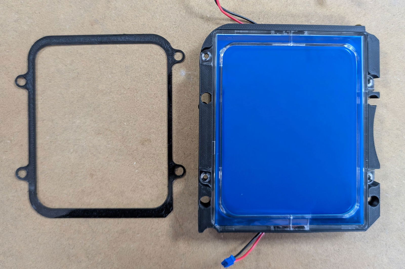
Transilluminator Seal (left), Transilluminator Assembly (right)
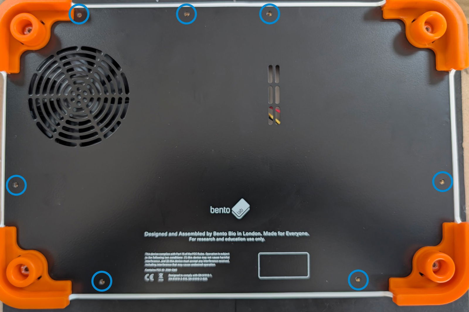
Step 1: Take off the baseplate to open Bento Lab
Use a T8 screwdriver to unscrew the 7 screws of the baseplate at the bottom of the Bento Lab. Remove the baseplate and put it to the side.
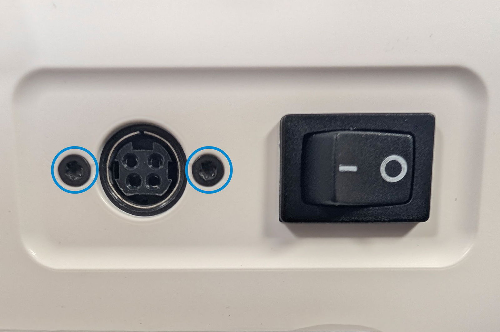
Step 2: Disconnect components
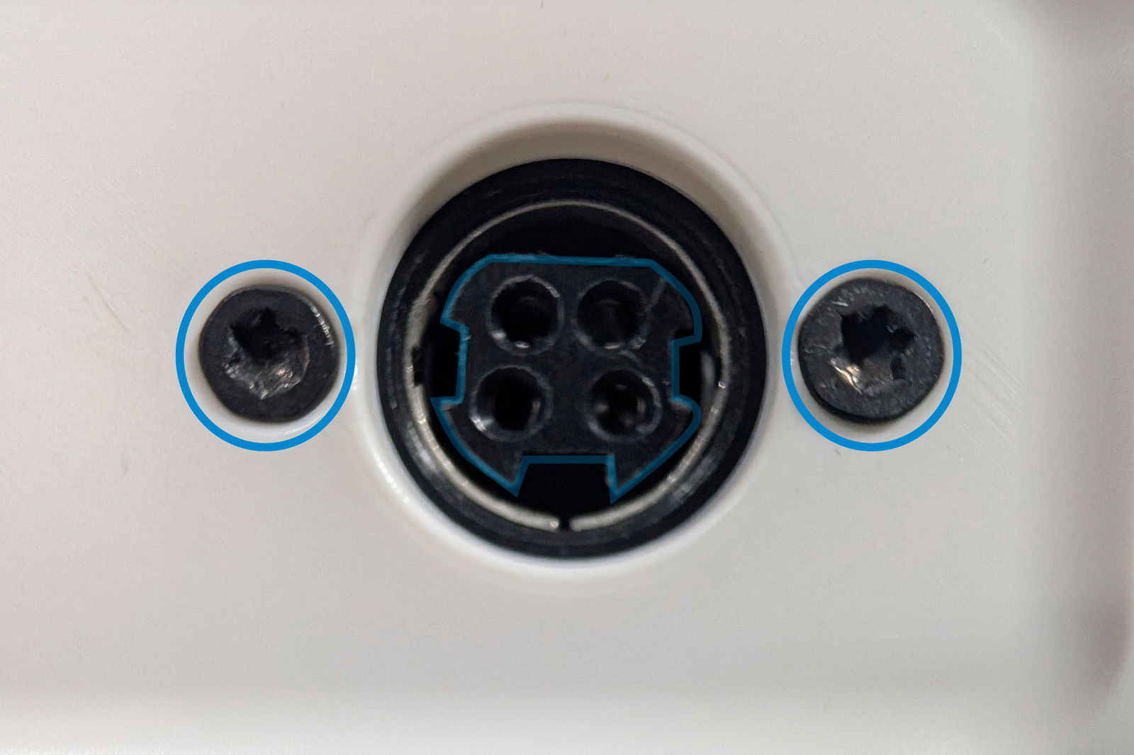
Using a T8 screwdriver remove the 2 screws holding the power connector in place.
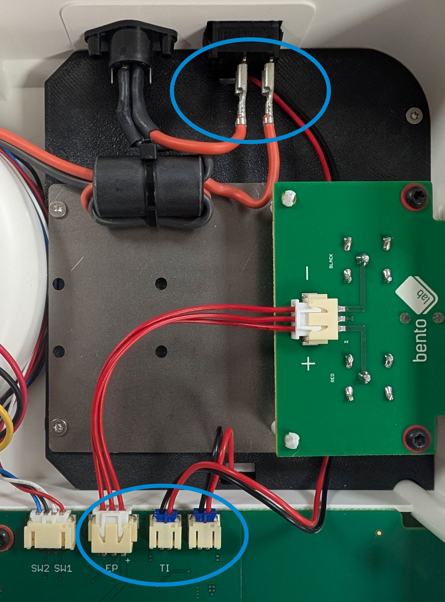
Next, disconnect the power switch from inside the case: Use a pair of pliers to firmly pull both of the silver connectors from the back of the power switch.
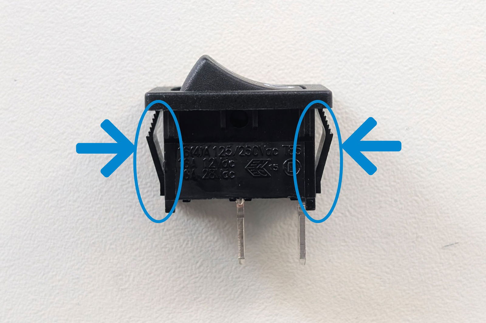
Next, push the power switch out of the case: Use the same pair of pliers to squeeze the black flaps on the side of the switch so that it can be fully pushed out.
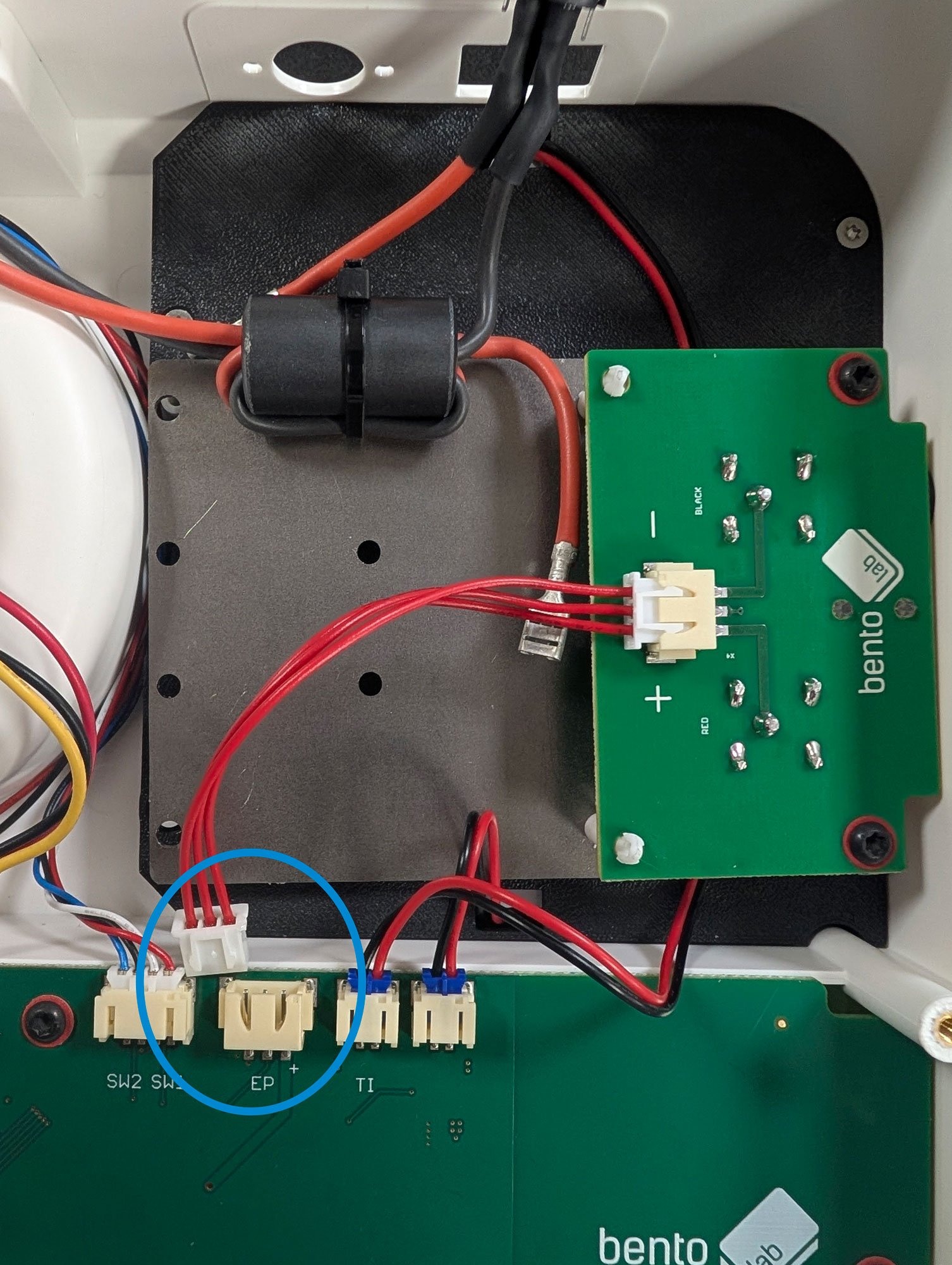
Disconnect the electrophoresis board from the main board. This can be done by hand or with a pair of pliers.
Now use a T8 or PH2 screwdriver (depending on your Bento Lab version) to unscrew the metal plate of the electrophoresis board assembly.
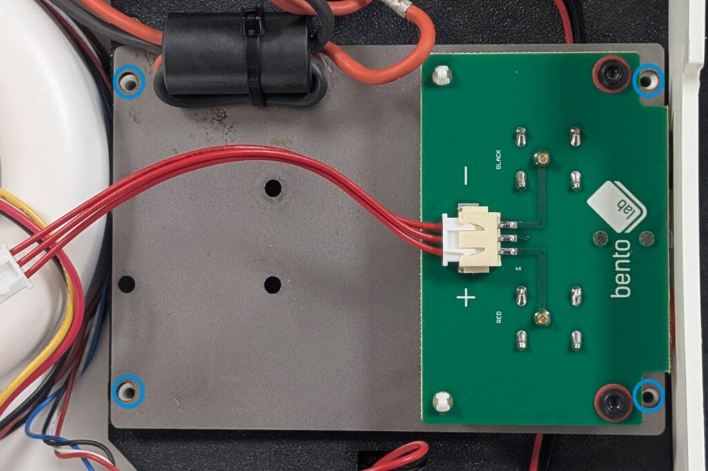
The assembly can then be removed by pulling it up by the left side. The board will still be connected to the Bento Lab. Place it on top of the centrifuge motor so it doesn’t interfere with the next steps.
Step 3: Remove the Transilluminator
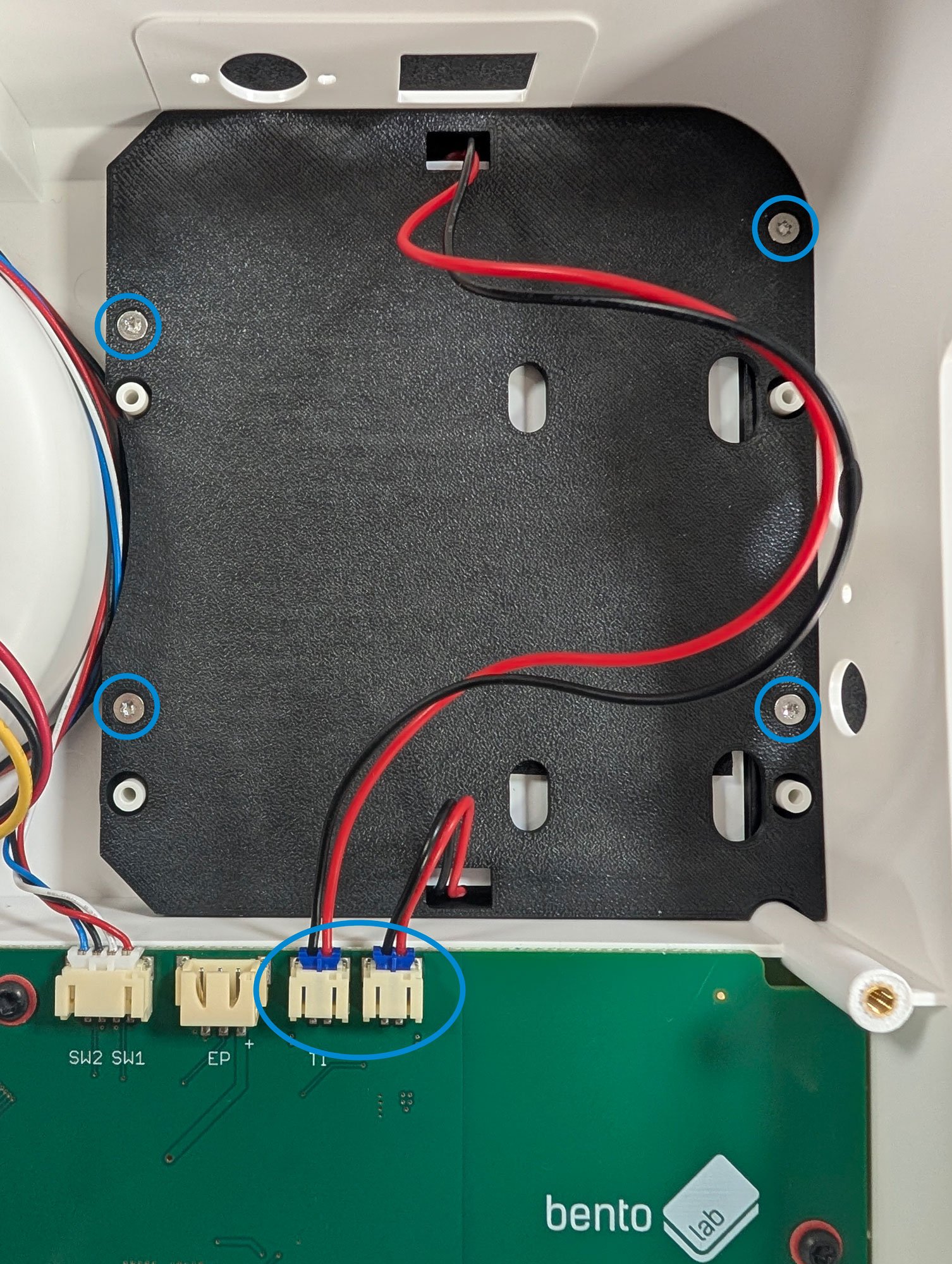
Unscrew the 4 screws holding the transilluminator in place. Use a T8 or PH2 screwdriver depending on your Bento Lab version. Next, disconnect the two wires. This can be done by hand or with a pair of pliers.
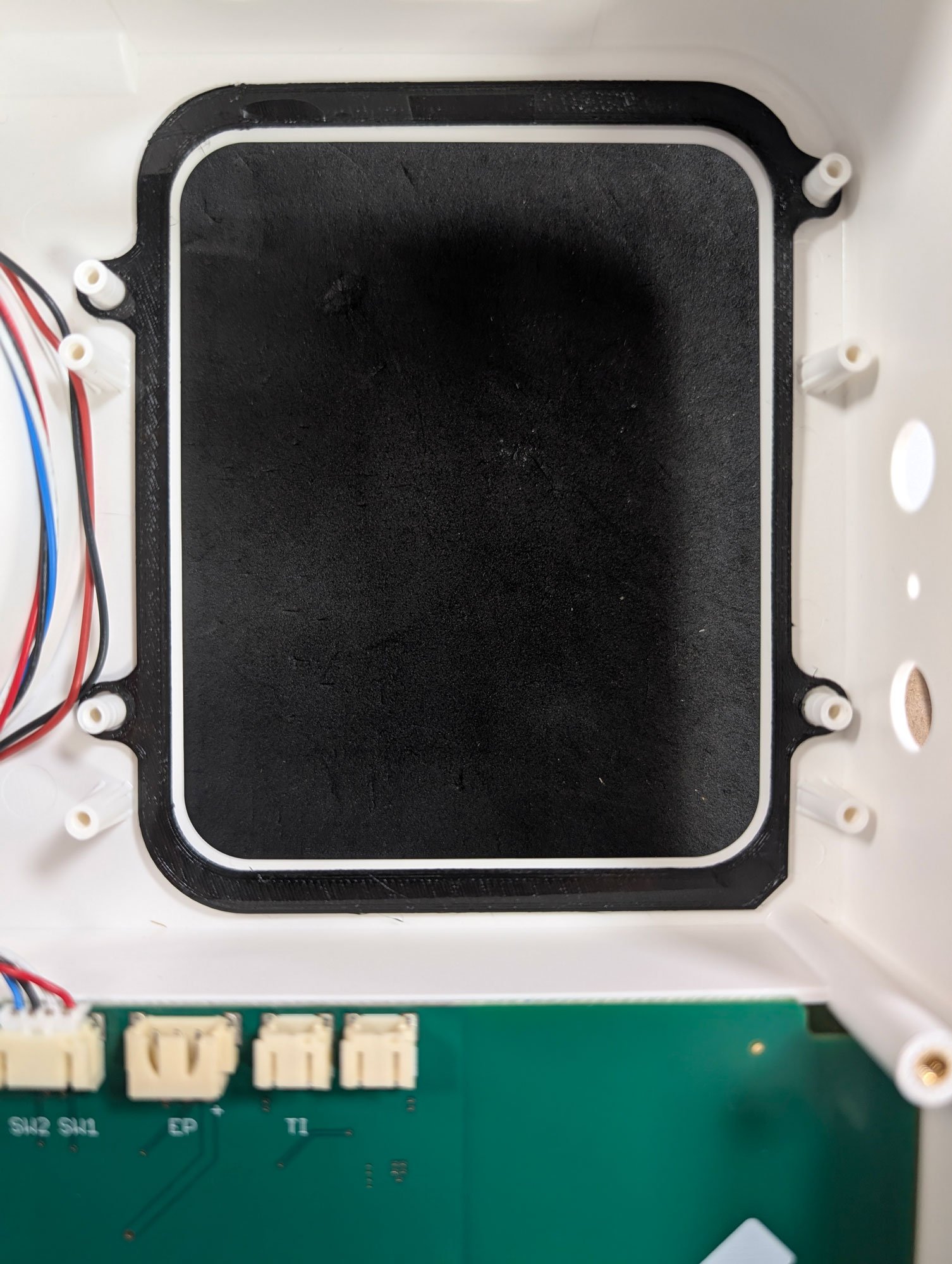
Step 4: Insert the Transilluminator Seal
Align the holes with the plastic pegs. It should lay flat with the notch pointing towards the bottom right.
Step 5: Installing the new Transilluminator
To install the new transilluminator, place it on top of the seal. Fasten it using the original screws.
(Note: Fasten each screw until you feel resistance, then stop to avoid stripping the plastic).
Now you can plug the wires back in the two right connectors on the board.
Step 6: Reinstalling the Electrophoresis assembly
First, position the assembly back so that the red and black electrophoresis connectors are aligned with the holes: It is easiest to tilt the assembly in order to insert the connectors in the holes. When the assembly is in position, screw in the metal plate (same screws as previously).
Reinstall the power switch: Press the switch into the case from the outside, making sure that the 2 prongs are on the right side of the case.
Next, screw the power connector back in from the back of the case. Use a T10 screwdriver for the two small screws. The orientation of the connector should be as shown in the photo (assuming the case is upside down).
Reconnect the power switch: The wire that comes directly from the connector belongs to the left prong, the wire that comes through the large ferrite (connected to the metal plate) belongs to the right prong. The red wires can be connected to the prongs by hand or with the assistance of pliers if necessary.
Finally make sure that everything is connected to the main board.
Step 7: Close the Bento Lab
Use the original screws to close up the Bento Lab. Make sure that the feet are correctly placed.
Need help?
If you have any issues during the upgrade, please don’t hesitate to contact us. We’re happy to guide you through the process or schedule a call if needed.